The Commodore Club of the Netherlands published an impression of the last meeting.
Next meeting will be on December 21th in Maarssen (near Utrecht)
The Commodore Club of the Netherlands published an impression of the last meeting.
Next meeting will be on December 21th in Maarssen (near Utrecht)
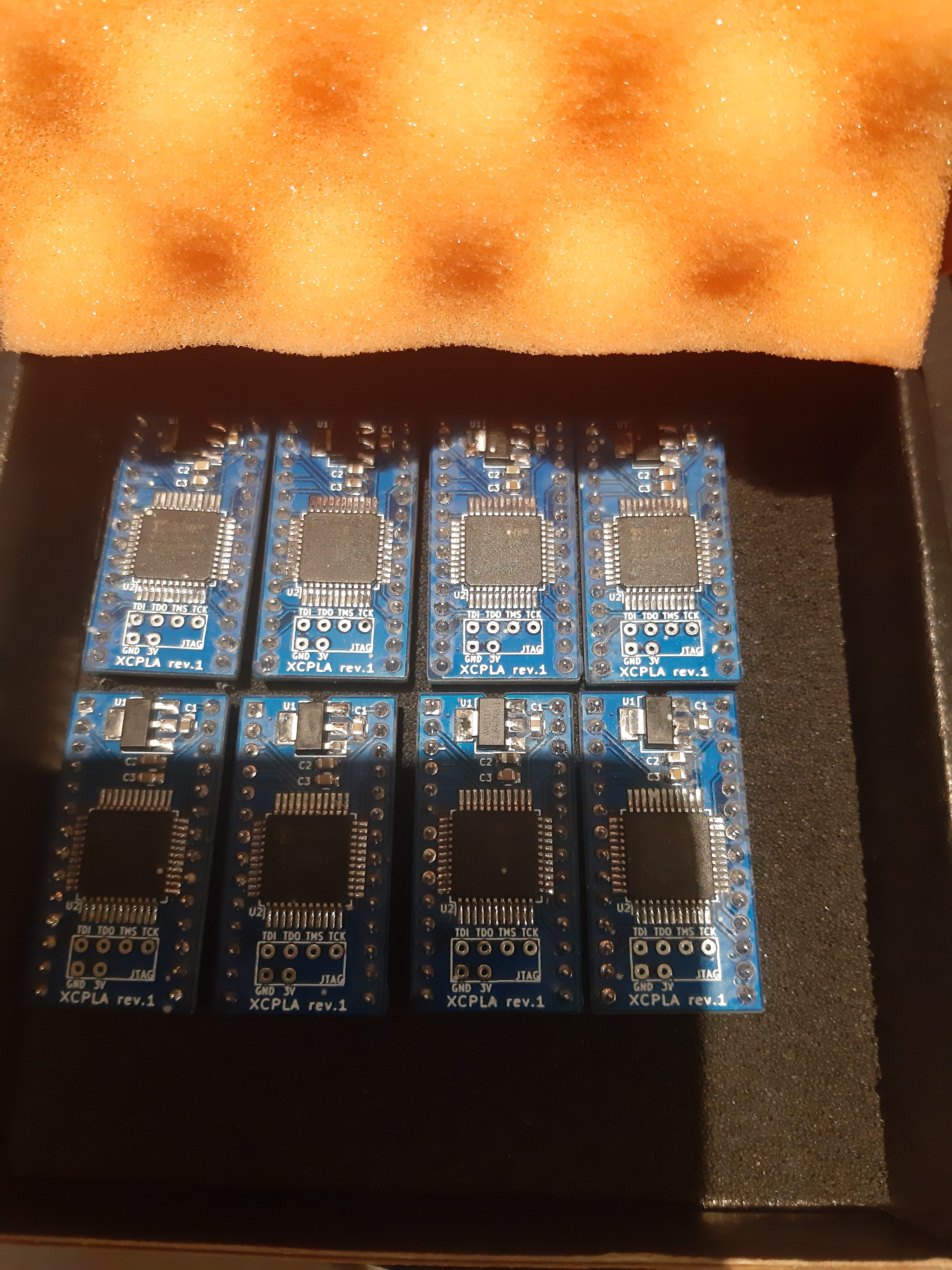
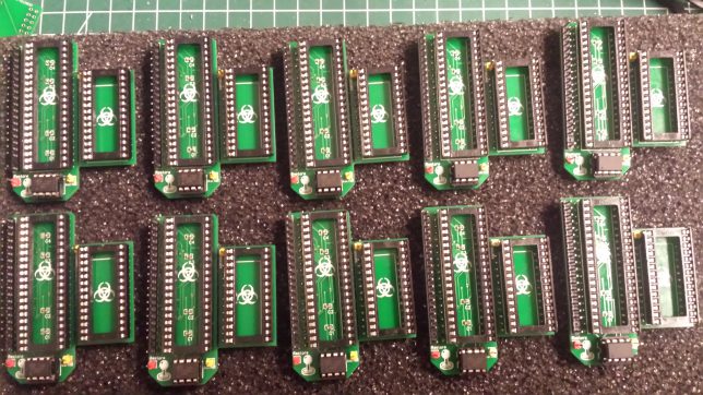
Last meeting of the Dutch Commodore Club (near Utrecht) we run out of PLA chips.
Searching the web I came across the website called hackup that used an existing opensource design to create a drop in replacement.
So I decided that I should build some, check them and use them to fix some C64 at the club (I normally can be found next to the repair corner, helping repairing).
This version of XCPLA is for the C64, but with other HDL code it should also work in other systems.
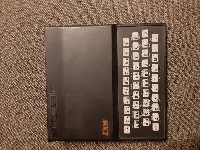
This weekend it will be Sinclair take over, so I will bring my zx81 to try to fix them.
Last couple of months I’m very busy with all kinds of little projects.
I’m looking through my stuff, collected over the last 20 years, My son is getting older and needs more space so I need to move my computers and other equipment to another room.
I also received a broken ZX81 (dead ULA and broken keyboard membrane), I already got another main board to check if it has a working ULA.
Another thing I received is a broken 1551, I think the TIA (6525) in the drive is broken, as this chip is rare, I need to find another way to replace it (CPLD ?).
I created about 15 pieces of the JoySwap to be sold, but currently I’m still writing a little installation manual.
I ordered some PI1541 boards and currently I’m waiting for the parts, the PI1541 looks very promising.
Last night I finished building the release version of joyswap.
This version will also swap the mouse and paddles.
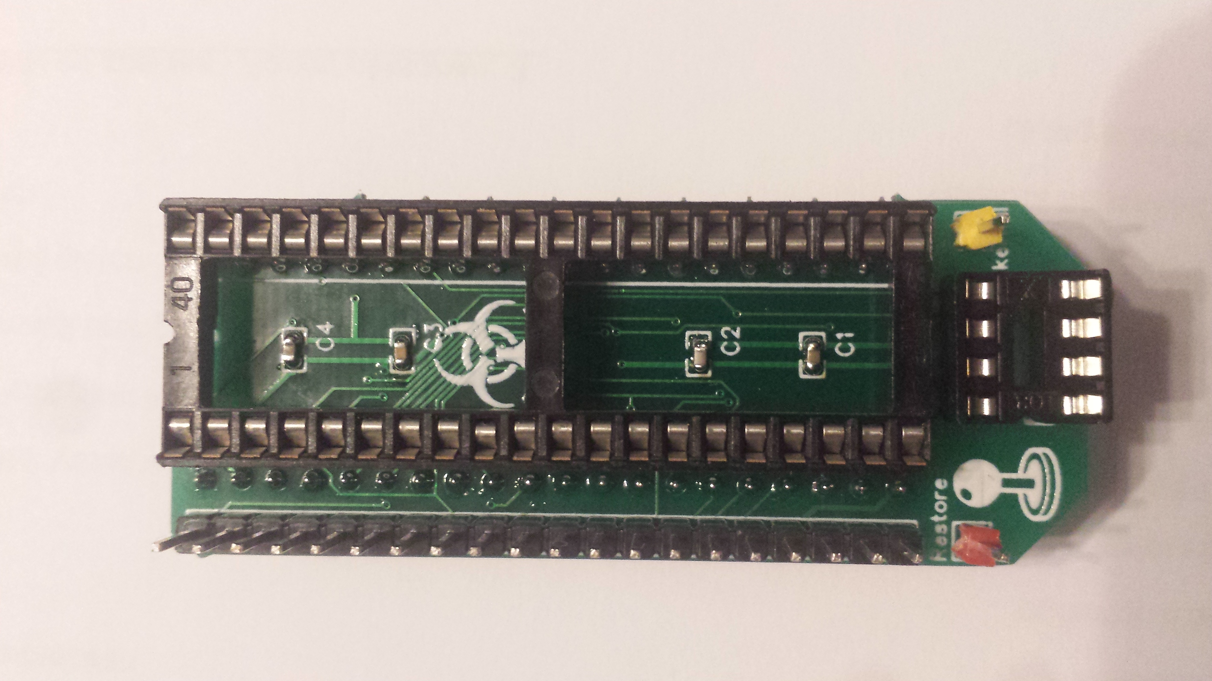
Last week I received 10 pieces of my revision 2 Joyswap PCB’s.
I started to build them all, but soon found out I only had 2 40 pin sockets, so I currently only finished 2 of them.
This revision also swaps the control lines of the 4066 chip that controls the mouse and paddles.
So now it will not only swap the (digital) joysticks but also the paddles and mouse from port.
When build in, pressing the restore key for about 3 seconds will swap the ports.
These ports will be reset to their normal position when a reset of the C64 is detected.
holding the restore key for 5 seconds will swap the kernal (if kernal option is used) and resets the C64.
holding it for more than 10 seconds, the kernal state is stored in the eeprom of the attiny for next power up.
more info here .
last night I finished the prototype of “JoySwap”.
JoySwap is a internal joystick switch that swaps the joystick ports at a (3 sec.) press on the restore button.
Next to the swapping of the joystick ports it can also switch between two kernal roms and store the selected rom for next power up.
you can read the complete story here
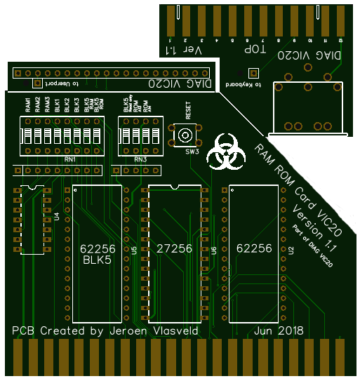
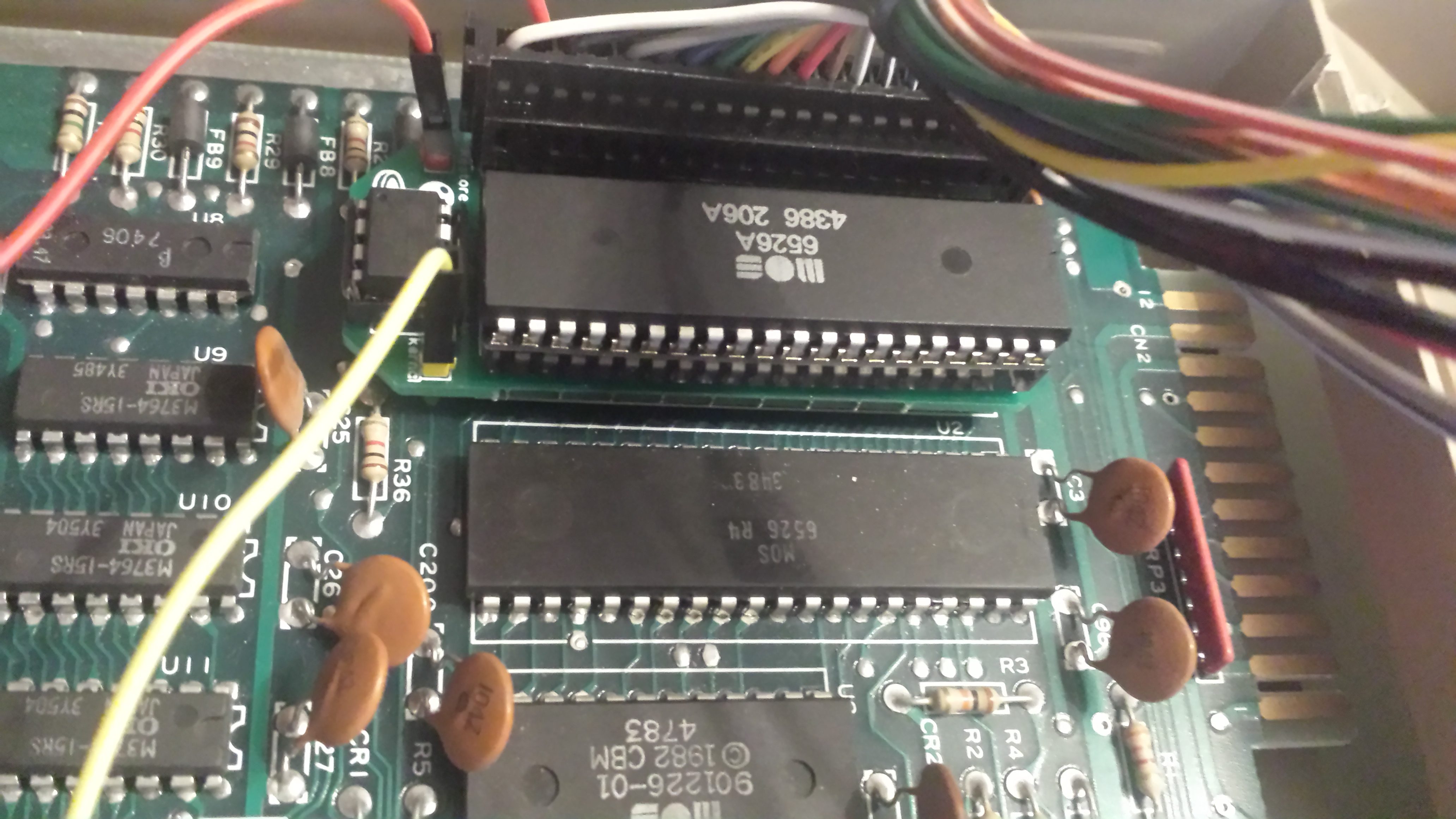
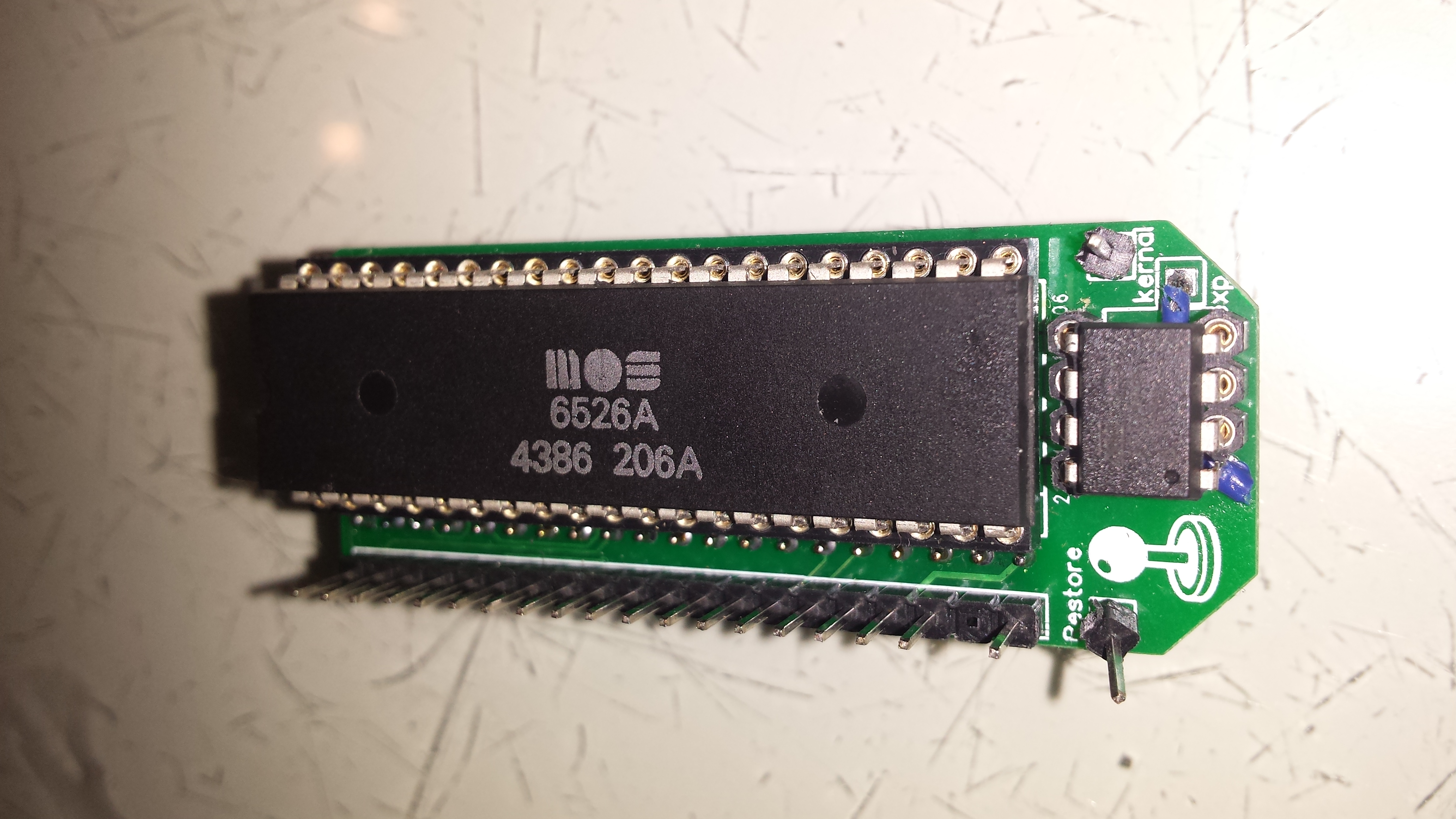
Last week I finished my Vic 20 Diagnostic kit.
The cartridge can also be used to expand the memory with a total of 35Kb.
I made this cartridge on request of a fellow club member.
More about this Diagnostic kit kan be found here.
The move of the website is now finished.
Everything should now work like it used to be.
Additional I added an event list at the right side.
Please contact me for any issues or items to publish on the event list
I’m moving the website to a new provider.
This could cause some downtime while moving the site.
The reason behind the move is the bad service my current provider (mijndomein.nl) gives.
After migrating/updating their hosting servers last month (22 june 2018), all links on my site were broken.
It took 5 days to get response from their support.
The responses clearly shows they don’t read the questions/requests.
last couple of months, I was very busy creating several new interfaces and converters.
one of these is the joystick converter for the 264 family systems.
this family has a 8 pin mini din as joystick connection.
a simple converter with only wires should work for a default joystick.
But joysticks that uses 5 volt for something like autofire would fail.
normally a joystick uses a switch between ground and a direction pin.
the 264 family uses a “select line” instead.
the converter I found on the internet used a latch (74f244) to control when the signals are send to the computer.
this way “more advanced” joysticks can be used.
for build details follow this link.
other things I’m building are a joystick switch to be build into the c64 and a diag264 harness.
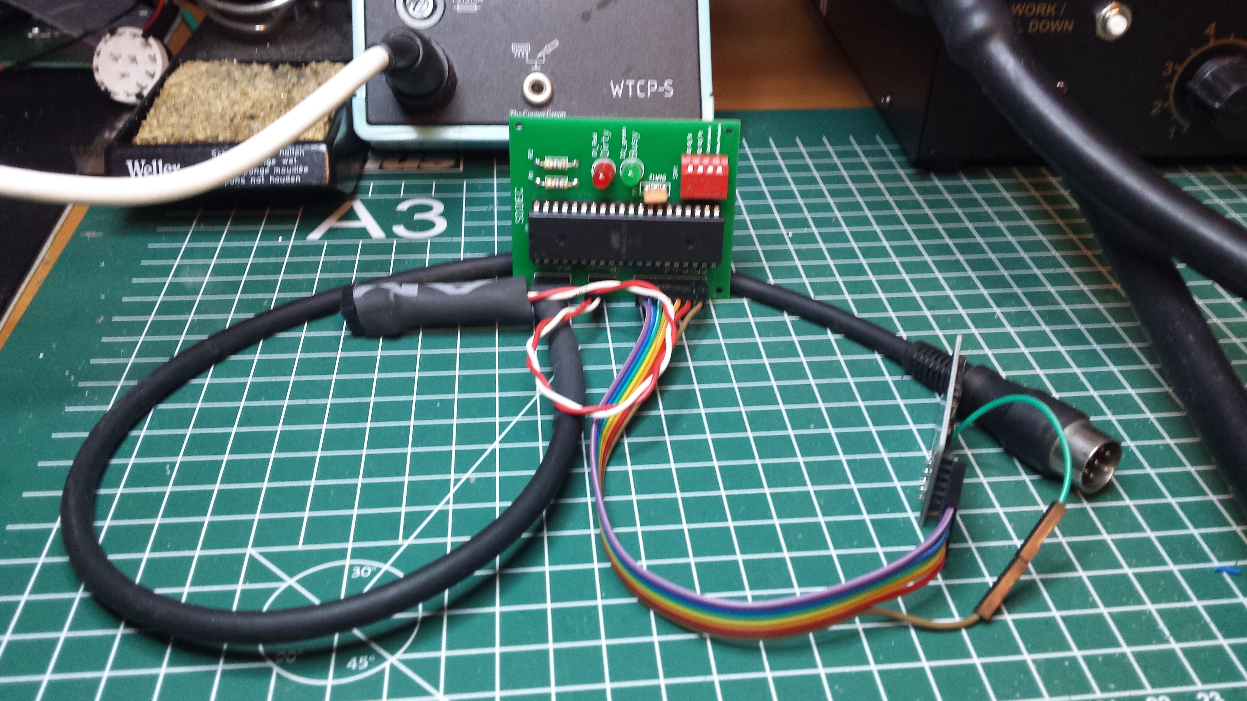
Last week I managed to complete my SD2IEC.
The PCB I created contained some little faults.
The silkscreen of the LEDs was wrongly positioned, and the DATA and CLOCK label of the serial port were swapped.
So I fixed the issues by swapping back the labels, and selecting a correct package for the LEDs (fault was in the component library).
The fixed version can be found on easyeda.com
I tried to program the AVR with AVRdude, but only got an error back (some sync error).
So finally I took my old STK500 development board, and downloaded AVRStudio from Microchip.
With this I could program the MCU and after hooking up the SD2IEC to my C64, I could access it like a drive.
(I uploaded the SW1 bootloader for the M1284P with the following High:0x92, Low:0xEF and Extended:0xFD)
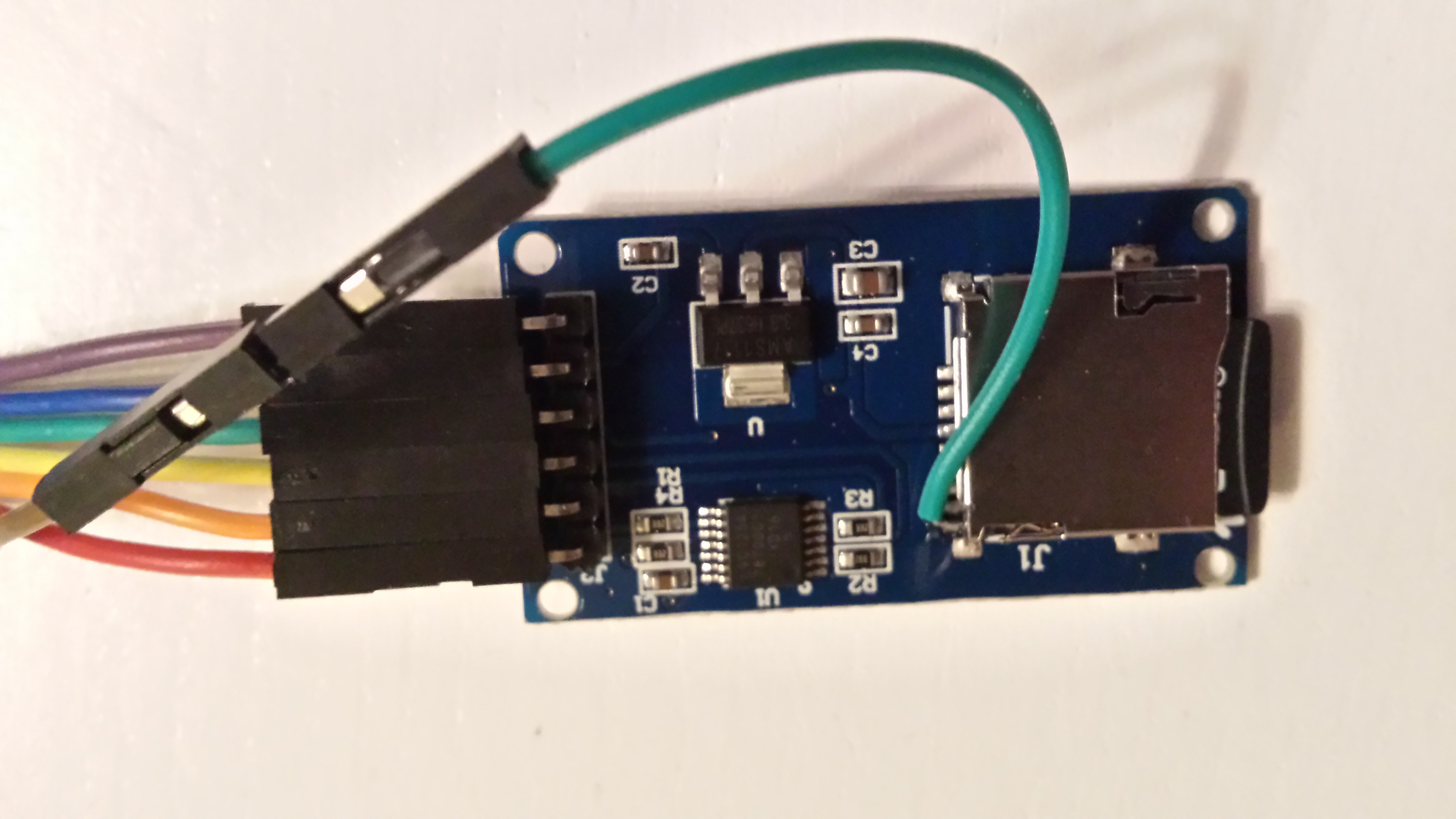
On the 2nd photo you see a modification of the mico SD module.
the module didn’t have the card detect signal on it’s pins, so I wired a wire for this signal.
the card detect can also be controlled by the dip switches.
another signal that is not pressent is the write protect signal.
Micro SD cards don’t have this, so this is also handled by the dip switch.