on a meeting of the Commodore Club I got the question if I could make a diagnostic set for a VIC20.
So I looked around, and found out that there was a diagnostic set created by Commodore.
I found schematics and ROM images for the harness on the sites from Ray Carlsen end Bo Zimmerman.
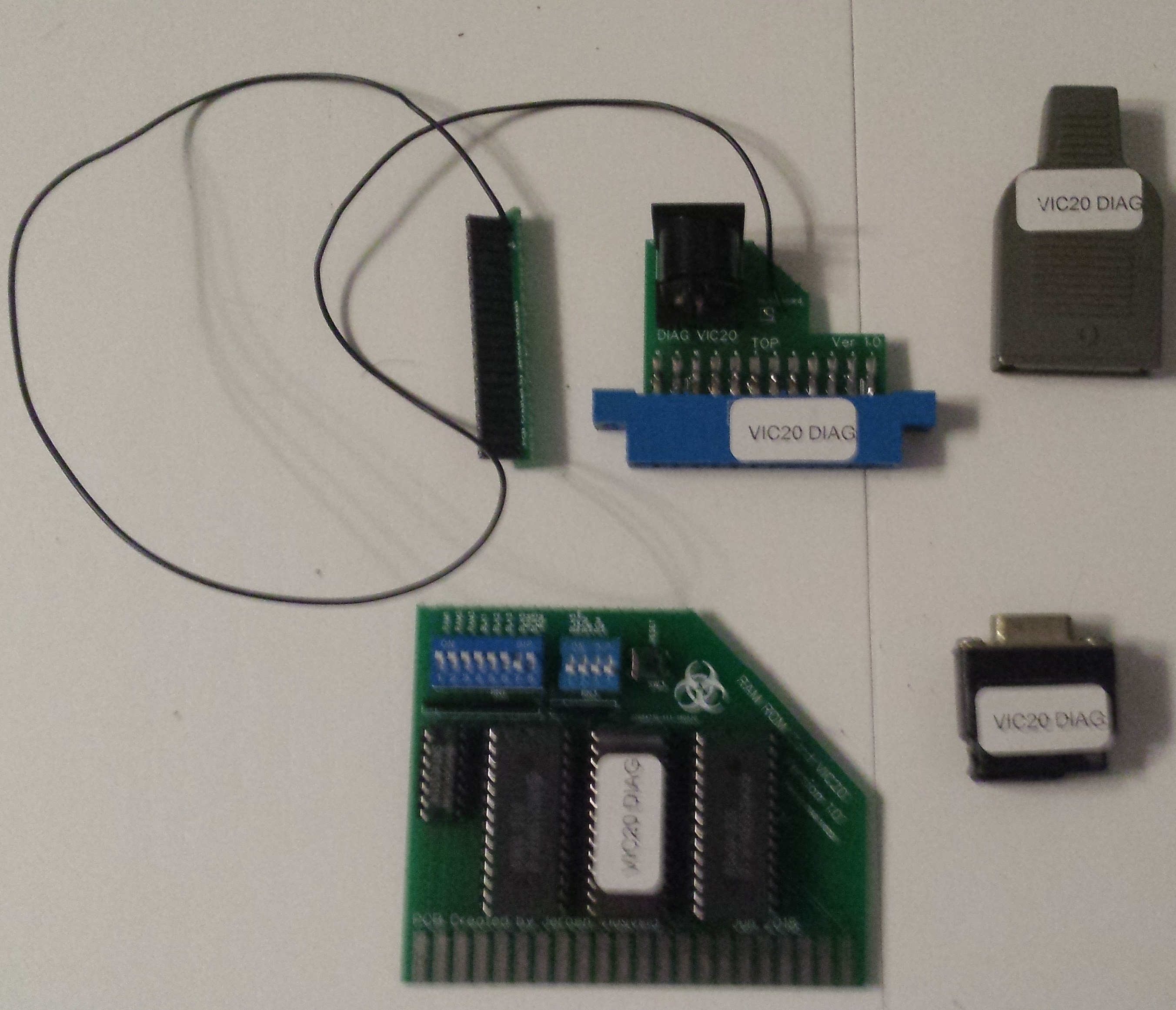
The diagnostic set can be divided in to 2 parts.
first a cartridge with the program and some memory.
second the test harness.
The diagnostic program is run from ROM in Block 5 and needs a 3k expansion.
So I started to look for expansion cartridges and found a schematic from Ruud Baltissen.
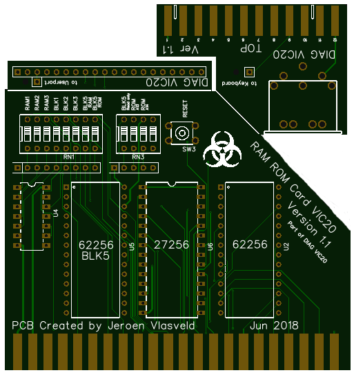
I did some tweaking and came up with a (35Kb) memory expansion cartridge with a ROM option.
The ROM is a 32Kb eprom that is divided into 4 8Kb parts (selectable by a dip switch).
The ROM can also be disable, and RAM could be enabled in block 5 instead.
The RAM in Block 5 can be put to read only, so a ROM emulation can be done.
The Cartridge contains 2 RAM chips of 32K, so a total of 64Kb, but only 35Kb is used.
maybe the I/O2 and I/O3 memory space can be added to add an additional 2Kb later.
RAM 1,2 and 3 and blocks 1,2,3 and 5 can be switch on or off by the dip switches.
Make sure you don’t enable ROM and RAM at the same time in Block 5, there is no protection to prevent this.
I don’t think it will destroy the VIC20, but it would certainly give problems as ROM and RAM will both try to set the address lines on a read.
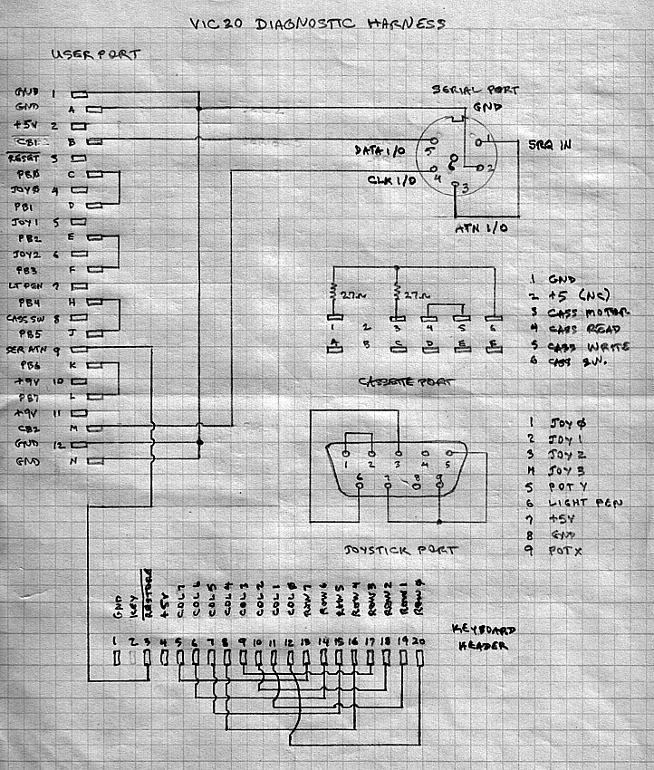
The harness is not more that some connectors that connect to the various ports of the VIC20 and only uses 2 resistors.
The Tape and Joystick connectors don’t connect to other ports and only uses some shorts/resistors between the pins, so I didn’t make any circuit board for them.
The Serial port is connected to the userport so I made a seral port connector on the PCB of the userport so a normal serial cable can be used to connect the serial port and userport.
(First revision I made a mistake with the pin numbering of the serial port connector, this should be fixed in the new 1.1 revision but it’s not tested).
The keyboard connector uses it’s own PCB, and is only connected to the userport PCB with just 1 wire.
Make sure you insert the connector the correct way.
It seems that the diagnostic software will detect if there is the test plug on the keyboard connector, as it will not fail when it’s not connect.
I think this is done because the Keyboard connector is the only one inside the VIC20, and this way you can test the VIC20 without opening the it.
The eprom for the contains 4 banks of 8Kb, as the ROM image for the VIC20 Diagnostic is only 4Kb, I just put 2 images after each other.
as I don’t have any tool in mind to use right now, I programed the eprom with the follow images:
2x NTSC Diag + 2x PAL Diag + 2x NTSC Diag + 2x PAL Diag.
Circuit board and schematics can be found on my easyeda project page.
of course building and using this interface and harness will be on your own risk.
explanation of dip switches
RAM1 – enable or disable 1K memory at $0400-$07FF
RAM2 – enable or disable 1K memory at $0800-$0BFF
RAM3 – enable or disable 1K memory at $0C00-$0FFF
BLK1 – enable or disable 8K memory at $2000-$3FFF
BLK2 – enable or disable 8K memory at $4000-$5FFF
BLK3 – enable or disable 8K memory at $6000-$7FFF
BLK5 RAM – enable or disable 8K memory at $8000-$BFFF *
BLK5 ROM – enable or disable 8K ROM at $8000-$BFFF *
BLK5 Writable – make RAM in BLK5 writable (ROM emulation) **
ROM A15 – select A15 line (selects ROM Bank)
ROM A14 – select A14 line (selects ROM Bank)
*Only one of the dip switches BLK5 RAM or BLK5 ROM may be enabled at the same time.
**wrong silkscreen text on version 1 and 1.1 of PCB