Commodore SX 64 I/O Board
- only two versions known (to me) 251106 Rev A and 251106 Rev 1, difference seems to be capacitor c9 that is missing in Rev 1.
- contains the logic and two CIA’s that the SX uses to communicate to external equipment like drives, printers and modems (and internal drive)
Integrated Circuits
| PCB Identifier | Chip Number | Remarks | Memory Location/bit |
|---|---|---|---|
| UC1 | 4066 | ||
| UB2 | 6526 | CIA 2 | $DD00-$DDFF |
| UB3 | 6526 | CIA 1 | $DC00-$DCFF |
| UD2 | 7406 | ||
| UE2 | 74LS74A | ||
| UE3 | 556 |
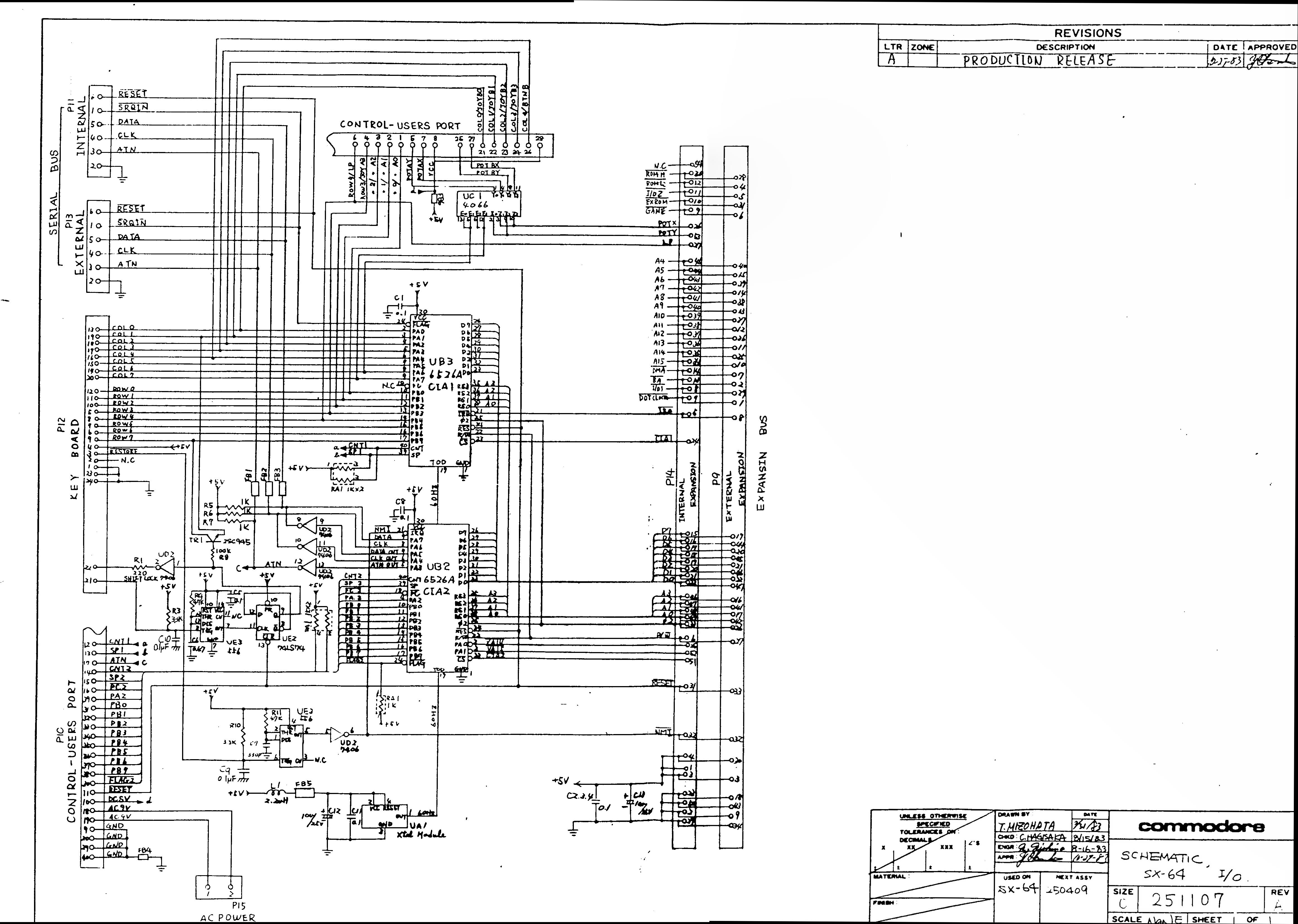
Schematics
Board Image
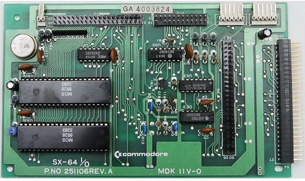
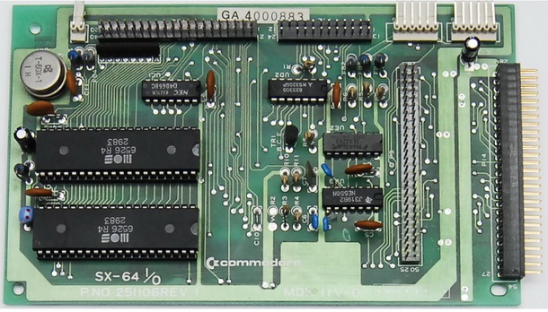
interesting about the C9 on the rev 1
I just ran into that issue installing a switchless jiffydos board
I think c= directly soldered it to the 556 on that version
if you look at the 2 picks of UE3 v1 has a resistor soldered on as a afterthought and the other its on the board properly marked as C9
um my bad UE3 has a capacitor …not resistor
shouldn’t try and type before my morning coffee
Schematic lists:
UC1 should be 4066
UE2 should be 74LS74
UB2 should be 6526A CIA
UB3 should be 6526A CIA
UD2 should be 7406
UE2 should be 74LS74
UE3 should be 556
Actually the circuit list is all wrong….
Dear Michael,
Thank you for telling me,
I listed the parts list of the floppy disk controller card instead of the I/O card.
I fixed the error.
Regards,
Jeroen.
HI,
a CIA in my SX 64 is giving me modem problems.
On the site of Ray Carlsen I found out I should replace CIA 2
So I looked for the right location of this CIA on this site.
Below “Integrated Circuits” it says:
UB2 = CIA 1
UB3 = CIA 2
But on the Commodore SX 64 I/O Board Schematics 251107 on this page it says:
UB2=CIA 2
UB3=CIA 1
One of them must be wrong?
Dear Sjoerd,
The table was incorrect, UB2 = CIA 2.
Be aware of the mistake in the SX64 userport, one of the 9 volt AC lines is connected to GND.
For some devices this connection needs to be “disconnect”.
See http://personalpages.tds.net/~rcarlsen/cbm/sx64/gnd-cut.jpg for a detailed image
Regards,
Jeroen.
Hi Jeroen,
Thanks for the remark about the userport problem.
The userport was already “fixed” in the last century.
Regards,
Sjoerd
I’ve been having trouble with my sx 64 not sending 5v to the user port at the back any ideas psu is fine no image display
Dear Ross,
the 5v of the user port comes direct from the connection of the I/O board to the CPU board.
so if the 5v line is ok, then check (refit) the connection between those boards.
it could also be a bad wire between the I/O board and connector Board, but that wouldn’t explain the black screen
also check SX repair notes from Ray Carlsen for more help
http://personalpages.tds.net/~rcarlsen/cbm/sx64/sx64.txt
This initial post is quite old but seems to be someonwhat active so I thought I would post my question. Does anyone know if the TOD crystal UA1 is 50HZ for the PAL SX-64? All the photo’s I’ve seen show part number T-60X-1. The schematic references 60HZ. As we know, the Commodore 64 derives its TOD clock from the 9VAC mains so TOD clocks on C64 PAL units are 50HZ. Of course its totally possible to tick the PAL C64 by using a US power supply in the US but the SX64 uses the crystal. I would also be curious if PAL boards us the same chip identifiers.
Dear Yochanan,
I tried to find a image that I took when doing a drive id mod on the I/O board.
But the photo’s didn’t show the crystal.
It shouldn’t surprise me when the PAL SX64 also has a 60 Hz Christal.
The kernal in the normal C64 detects if the system is PAL or NTSC, by checking the amount of screen lines (PAL has more screen lines), then writes to a register of the CIA ($DC0E) if the TOD signal is 60 or 50 Hz.
the SX64 has it’s own kernal, so this check could be changed to always write 60Hz to the CIA register.
But, I didn’t test this.
Hi Jeron,
Thanks for the response. I actually already found the answer. You are correct that both SX-64’s have a 60 Hz crystal. You are also correct about the Kernal, but only partially. Yes scans lines are counted to detect PAL/NTSC but it’s a misnomer that the Kernal sets the TOD clock frequency based on that PAL/NTSC detection. The kernel does use the timer during initialization, but it always sets the TOD clock frequency to 60 Hz for both CIAs. The last value the Kernal writes to $DC0E and $DD0E during initialization is #$01 and #$08 respectively for both PAL and NTSC systems thus bit 7=0 for both. Unless you use a modified scan line counting routine, it takes a CIA timer along with the stock Kernal scan line counting routine to detect the TOD clock speeds for all machines and video standards. Neither the stock Kernal scan line counting routine nor a Kernal signature alone is sufficient.