if you want to boot from an other drive than the default build in drive, then you will need a bootselector in your Amiga.
The Amiga selects it’s drives by pulling a select line low, all drives have it’s own select line.
So all what we need to do, is swap the lines when we want to boot from an external drive.
With this simple solution, there is a downside, when swapping the lines while the Amiga is turned on, it will not know that the drives are swapped and it will know another disk is ready, or even could write to the wrong disc (corrupting it), so operate the switch when the Amiga is turned off.
The select lines are generated by one of the CIA chips.
This CIA is identified on the Amiga 500 boards as the Even CIA (U8).
CIA stands for Complex Interface Adapter.
The CIA is a interface chip that can handle communication to the outside world and is in the Amiga responsible for the parallel/serial port, keyboard and other I/O.
The CIA 8520 that is found in the Amiga is the big brother of the CIA 6526 used in the Commodore 64.
Both share the same pinout, but the clock is stored in a different way.
The 1581 (3.5″ drive for the C64/C128) could have a 8520 or a 6526 as it did not use the clock.

The select lines we need are the _sel0 and _sel1. they are located on pins 13 and 14.
The easiest way to swap the lines is just to use a switch.

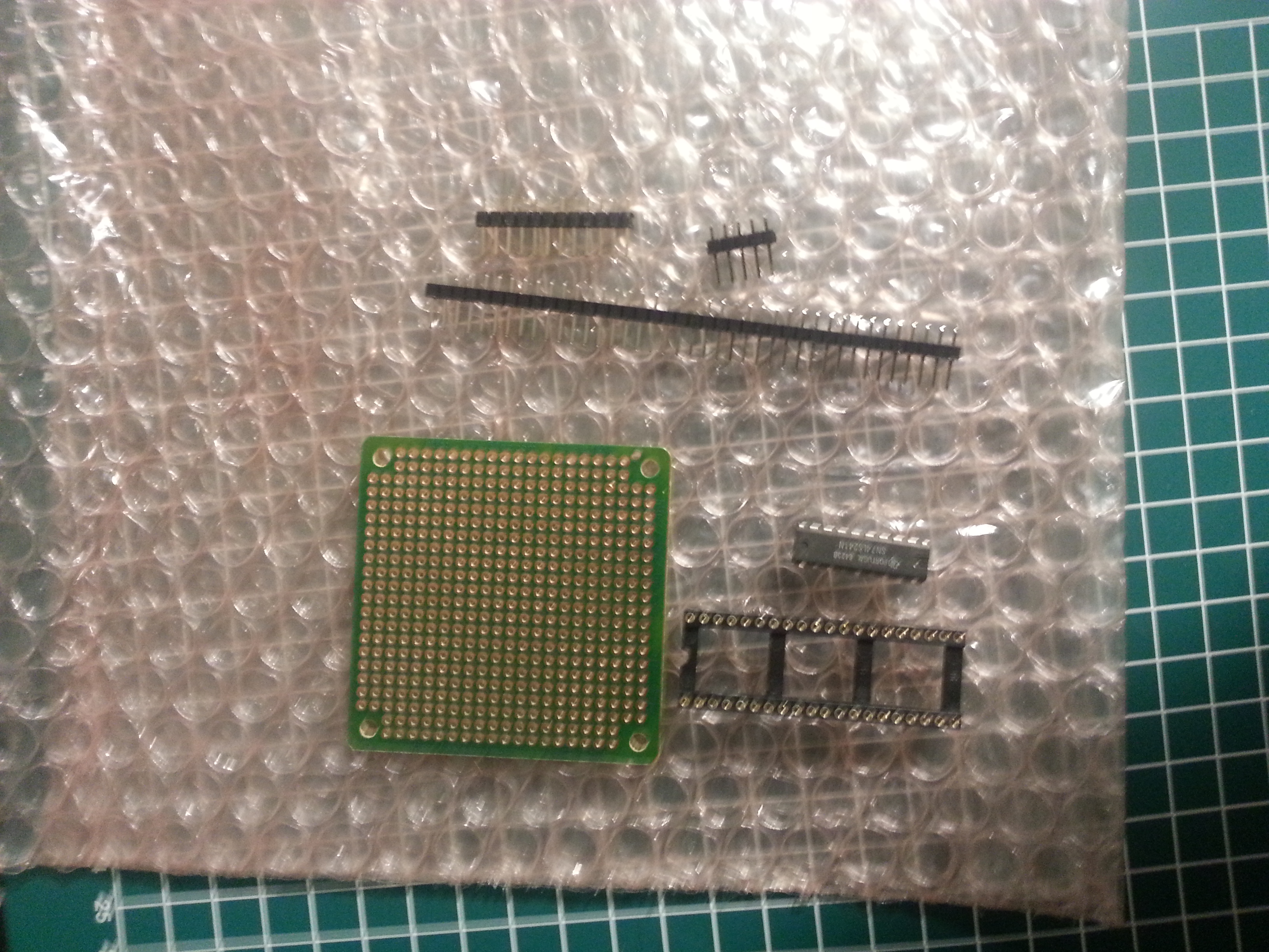
What you need..
- Circuit board
- 40 pins ic socket
- 40 pins single row header
- DPDT switch
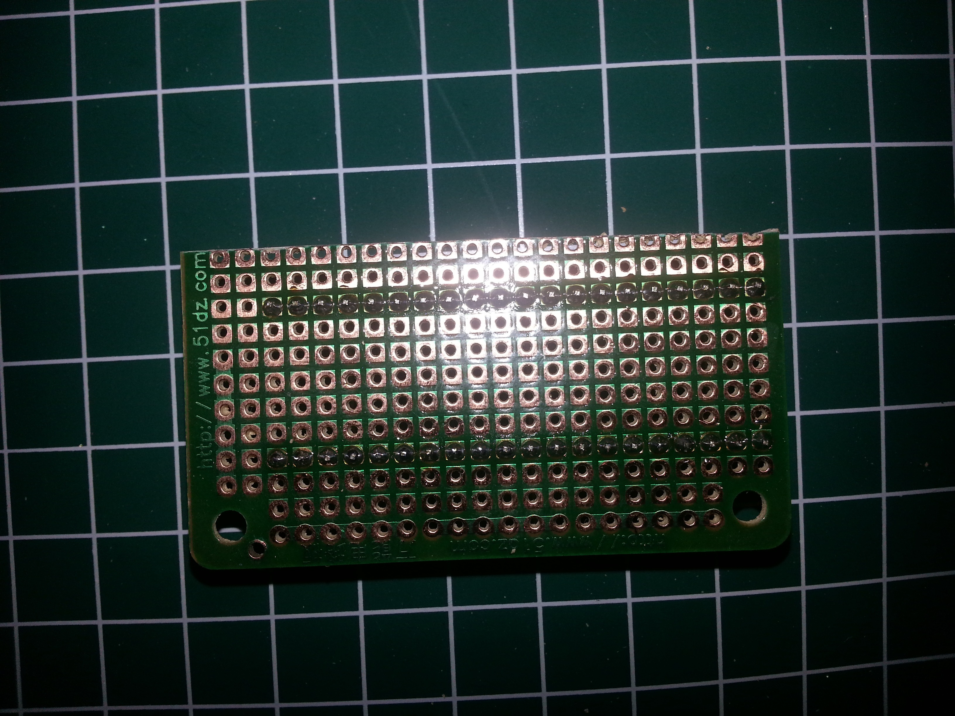
First divide the 40 pins header in 2 pieces of 20 pins.
Cut the board in the size of the 40 pins ic socket.
Solder the 2 pieces of 20 pins header at the same size of the ic socket.
now cut of the small part of pin 13 and 14 from the ic socket.
And solder the ic socket to the pins (at the solder side) of the header (Pins 13 and 14 should not be connected and have some space between the socket and header).
Take some wires and solder it to the pins 13 and 14 of the header and socket.
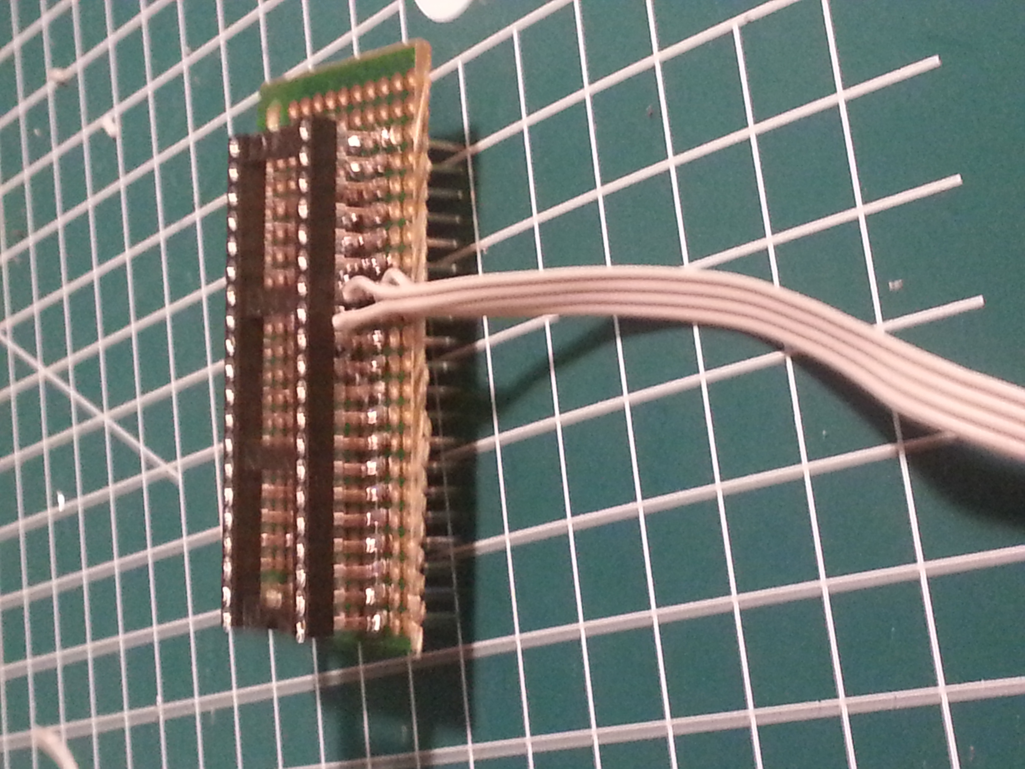
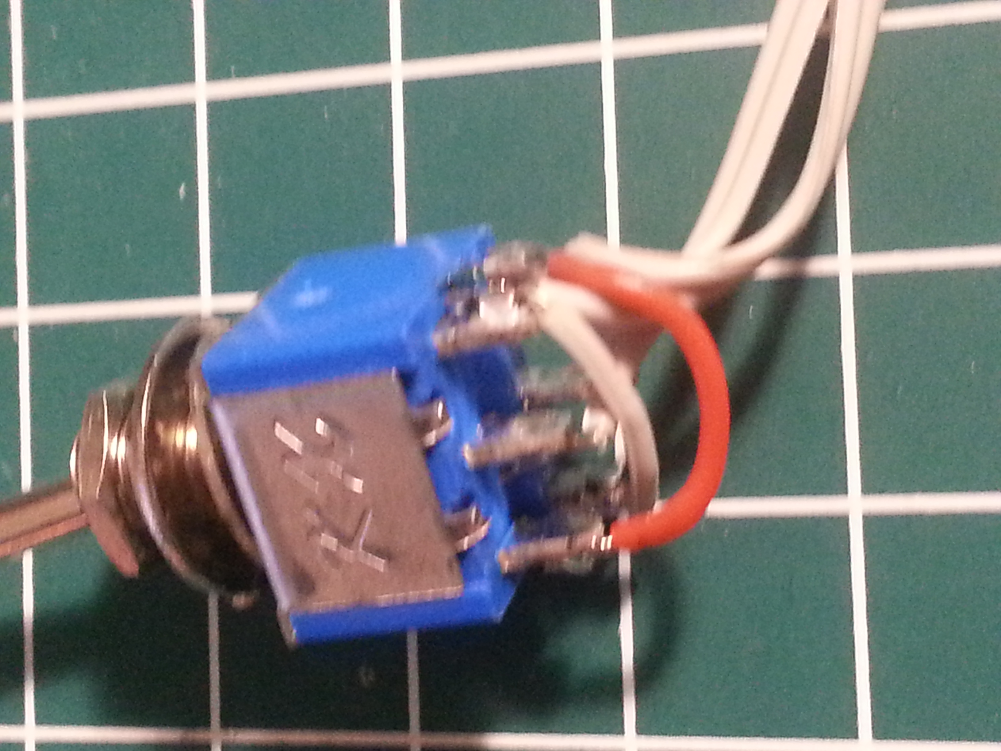
Solder the other side of the two wires from the socket to the middle contacts of the switch.
Solder the two wires that are still free to the contacts of one side of the switch.
Now take a little wire and solder it to one of wires you last solder to the switch, and solder it to the other side of the switch so that it swaps the pins (left on the one side should go the right on the other switch).
do the same with the other side.
now check for short circuits and remove the Even CIA from the mainboard (U8 near the floppy connector).
place the boot selector in the socket (mind the pin 1 markings).
place the CIA on the boot selector.
Drill a hole in the at the back of the Amiga (next to the joystick connectors) and mount the switch.
Check if everything is fine, and power on the Amiga and check if it is working.
I can’t get any Bubble Bobble rom (written to floppy disk) to work with this sort of configuration. It works when the internal drive is set to df0, but not when the external drive is set to df0.
Are you able to confirm this issue with your setup so I know if I’m doing something wrong?
Same issue with Giana Sisters