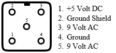
Power Connector
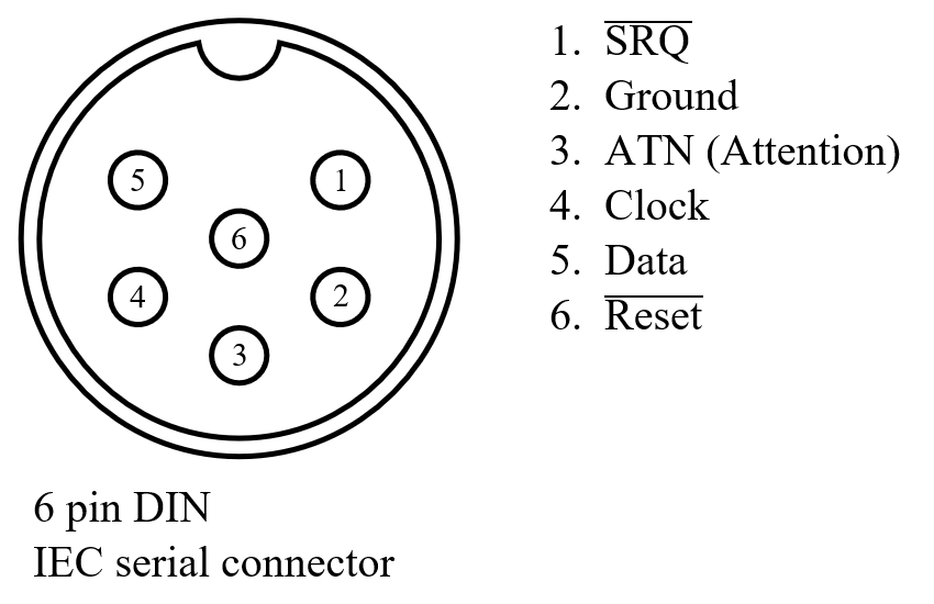
Serial Connector
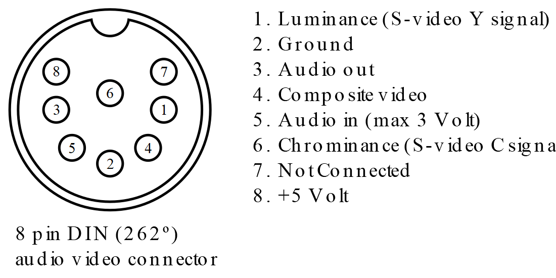
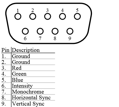
Audio / Video Connector
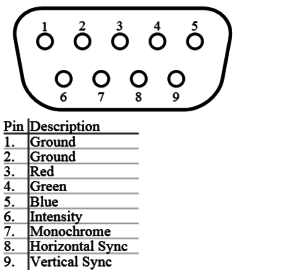
RGBI Video port (80 column video)
Joystick Connectors
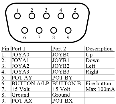
The Joystick ports are connected to CIA 1 in parallel to the keyboard matrix.
To read the direction from the joystick you can read the memory locations 56321/DC01 for port 1 and 56320/DC00 for port 2.
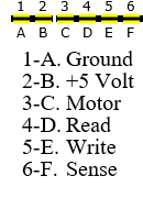
Datasette Connector
Userport Connector
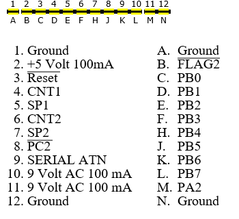
The userport PB0-PB7 is connected to the CIA 2 port B and is controllable by setting the right direction bits in the Data Direction Register Byte (DDRB) on address 56579 ($DD03).
And writing or reading the port on address 56577 ($DD01).
Note, when using the RS-232 functions (open 2,2,2) will change the DDRB.
I think pins 4 and 5 in the above video pinout must be reversed. The 64 and the 128 have the same pinouts, and as far as I know every Commodore computer after the 64 has the same pinouts, except possibly pins 7 and 8.
Dear Michael,
Thank you for your comment.
Image is corrected.
Regards,
Jeroen.
My video cable has RCA plugs on the monitor end.